VJ5601M915MXBSR
www.vishay.com
Vishay Vitramon
Revision: 28-Mar-12
4
Document Number: 45208
For technical questions, contact: chipantenna@vishay.com
THIS DOCUMENT IS SUBJECT TO CHANGE WITHOUT NOTICE. THE PRODUCTS DESCRIBED HEREIN AND THIS DOCUMENT
ARE SUBJECT TO SPECIFIC DISCLAIMERS, SET FORTH AT www.vishay.com/doc?91000
VJ5601M915 ASSEMBLY GUIDELINES
1. Mounting of antennas on a printed circuit board should
be done by reflow soldering using the profiles shown
(Figures 8, 9, and 10)
2. In order to provide the adequate strength between the
antenna and the PCB apply of a dot of heat cured epoxy
glue in the center of the footprint of the antenna prior to
soldering the antenna to the board. An example for such
glue is Heraeus PD 860002 SA. The weight of the dot
should be 5 mg to 10 mg.
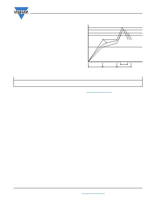
Fig. 10 - Soldering IR Reflow with SnAgCu Solder
Note
(1)
The VJ5601M915 kit is available for evaluation. For samples, please contact mlcc-samples@vishay.com
.
0
50
100
150
200
250
300
T
C)
Time
60 s to 120 s
30 s to 60 s
Max. temperature
Min. temperature
Sn-Ag-Cu solder paste
60 s to 120 s
60 s to 120 s
ORDERING INFORMATION
VISHAY MATERIAL
PACKAGING QUANTITY
VJ5601M915 Chip Antenna
VJ5601M915MXBSR
1000 pieces
VJ5601M915 Evaluation Kit
(1)
VJ5601M915MXBEK
1 kit
发布紧急采购,3分钟左右您将得到回复。
相关PDF资料
VJ6040M011SXISRA0
ANTENNA 470-860MHZ UHF SMD
W1028
ANTENNA 5.15/5.85GHZ R-SMA BL 5"
W5012
ANTENNA 900MHZ CONN STRGHT RP-SM
WA.500W.301151
RF ANTENNA
WLP.2450.25.4.A.02
ANTENNA 2.45GHZ PATCH
WM.90.A305111
RF ANTENNA
WPC.25A.07.0150C
CER PATCH W/INTEGRAL GND
WS.01.B.305151
ANT DUAL BAND WI-FI/ZIGBEE
相关代理商/技术参数
VJ5A0001-1ZZ00-000
制造商:Carling Technologies 功能描述:V-SERIES ROCKER SWITCH - Bulk
VJ5A000B-AZB00-000
制造商:Carling Technologies 功能描述:V-SERIES ROCKER SWITCH - Bulk
VJ5A000B-AZC00-000
制造商:Carling Technologies 功能描述:V-SERIES ROCKER SWITCH - Bulk
VJ5A4111-1EE00-000
制造商:Carling Technologies 功能描述:V-SERIES ROCKER SWITCH - Bulk
VJ5A4111-6RR00-000
制造商:Carling Technologies 功能描述:V-SERIES ROCKER SWITCH - Bulk
VJ5AA601-15ZMH-100
制造商:Carling Technologies 功能描述:V-SERIES ROCKER SWITCH - Bulk
VJ5AA80B-AKC00-000
制造商:Carling Technologies 功能描述:V-SERIES ROCKER SWITCH - Bulk
VJ5AA80B-AWC00-000
制造商:Carling Technologies 功能描述:V-SERIES ROCKER SWITCH - Bulk
